Article Index
- Video Instructions
- Changing Approach Feet
- Approach Foot Installation
-
Adjusting Hopping Foot Stroke on 18” and 22” Gammill Machines
- Setting the Hopping Foot Stroke and Height for the Approach Foot System (18- and 22-inch machines)
- Troubleshooting Hopping Foot Adjustments
Video Instructions
There are a variety of Approach hopping feet available through Gammill. The foot can be changed by following these steps:
STEP 1: If the machine is not already in the needle up position, rotate the handwheel to raise the needle to its highest position.

STEP 2: Use the hex screw driver tool to loosen the adapter screw 2 turns. Slide the hopping foot toward the back of the machine to remove it.

STEP 3: Install the new Approach foot by inserting it into the adapter from the back and sliding it forward. Use one hand to stabilize the foot while tightening the adapter screw with the hex screwdriver tool. The foot will self-align with the adapter as you tighten the screw.

Approach™ Foot System Installation Instructions
Tools required (not provided):
3-6 double ended cotton tip swabs
Medium size flat head screwdriver (to fit presser bar clamp screw)
Small size flat head screwdriver (to fit existing needle set screw)
5/16” open end wrench
7/16” open end wrench
Approach Foot System contents:

(note, F: Foot Stroke Sticker Set will not be used on 18" and 22" machines).
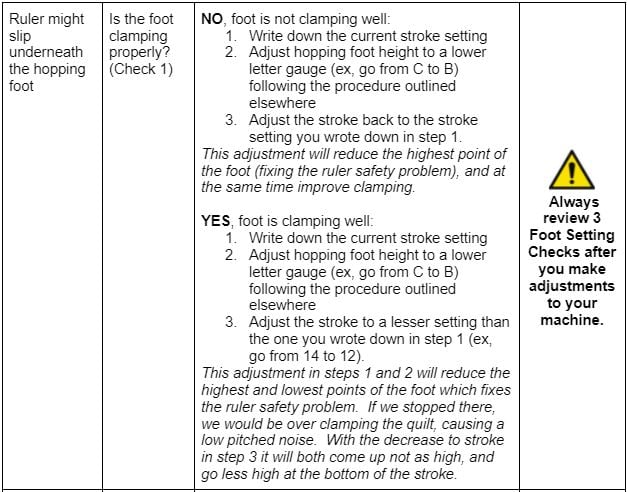
STEP 1: Fully remove the existing needle set screw from the machine (and remove the needle also). Install the new black needle set screw provided in your Approach kit into the lower of the 2 holes in the needle bar (H) (Fig. 1). Do not install a new needle at this time.

STEP 2: Using a 5/16” open end wrench, loosen and remove the hopping foot from the hopping foot bar. Looking from the top, the hopping foot is loosened by rotating clockwise. (Fig. 2). In some cases the bottom of the foot might rub against the needle plate when unscrewing the foot. Some light contact will not prevent foot removal, but it may be necessary to raise the hopping foot bar slightly in order to complete this step. If necessary, refer to step 6 for information about changing the height of the hopping foot bar.

STEP 3: Wipe all oil and debris off of the exterior of the hopping foot bar. To remove the oil and debris from the threads up inside the end of the hopping foot bar, cut several double-ended cotton swabs in half so that you have created single-ended swabs that are only half as long as before (Fig. 3). Screw the fuzzy end of a cotton swab up inside the open end of the hopping foot bar and then unscrew it back out. It will emerge dirty. Continue to insert and remove swabs until swabs emerge nearly clean.


STEP 4: Attach the ruler foot (B) to the adapter (C) using foot screw (D) and the hex screwdriver tool (G). Shake LocTite container (I) vigorously for 30 seconds, then snap the end off to open. With the tip of the LocTite container oriented downwards and resting against the adapter threads, squeeze the container lightly to apply to the adapter threads until the threads are completely coated. (Fig. 4)

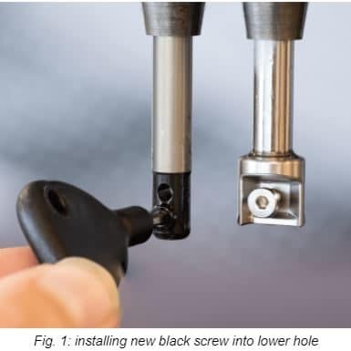
STEP 5: Screw the (wet with LocTite) adapter all the way into the presser bar until it stops (Fig. 5).

STEP 6 Remove the hopping foot bar clamp access rubber plug by pressing against the side of the rubber plug with a screwdriver (Fig. 8). Do not pry between the rubber plug and machine or the paint could be damaged
CAUTION: THE RULER FOOT (or open toe foot) MUST BE INSTALLED ON THE MACHINE BEFORE PROCEEDING

STEP 7 With the Ruler Foot or Open Toe Foot installed on the machine, loosen the hopping foot bar clamp screw with a flat blade screwdriver by 1/2 to 1 full turn. Don’t take the screw out. With the screw loosened, the bar for the hopping foot is free to rotate and free to move up and down (Fig. 9).

Adjusting Hopping Foot Stroke on 18” and 22” Gammill Machines
STEP 1: Remove the bobbin case and unthread the needle.
STEP 2: Remove the 8 screws and the inspection plate on your machine (Fig. 1)
STEP 2A: Some Vision machines require unplugging a wire (Fig. 2) if it goes thru the inspection plate. There is a small plastic locking clip (Fig. 3) on the underside of the connector (Fig. 4). To unplug, firmly squeeze that clip while gripping the plug and pulling straight out. Do not pull on the wires, pull only the plastic connector.

STEP 3: Turn the handwheel to raise the needlebar to the highest point if it’s not already there. The 2 screws that lock in your stroke adjustment will be facing you as shown in Fig. 5. They usually have a combination type screwhead that accepts either phillips or slot screwdrivers.
STEP 4: Loosen the 2 lock screws by 2 turns only (Fig. 6)

STEP 5: Turn the machine handwheel ¼ rotation so that the Locking Screws are facing straight up (12 o’clock).
STEP 6: Insert a 4mm or 5/32” allen (hex) wrench into the Stroke Adjustment Screw (Fig. 7)

STEP 7: Turn the wrench (counter-clockwise) until the screw stops turning. Your machine is now at maximum stroke position. Remove the wrench from the machine and turn the handwheel a couple of times to observe how large the hop of the foot is. This can be a great setting to use on a very fluffy quilt with the foot height set to the A or B Foot Height.
STEP 8: Turn the wrench 3 turns tightening (clockwise) until the screw will not turn anymore. Your machine is now at a zero stroke position. (if when turning your machine, it does a little reverse-hop with the foot slightly rising when the needle is going down, loosen the wrench ½ turn and that should be your zero stroke.) Remove the wrench and turn the handwheel a couple of times to see how the hopping foot just hovers without actually hopping. This setting isn’t useful for anything, you should always have some stroke so that it can properly clamp and hold the quilt.
STEP 9: This is a good time to experiment a little and play. Take a minute to turn that adjusting screw back and forth to different spots, pausing at various spots to turn the handwheel and observe how the stroke of the hopping foot changes. There are 3 full turns of the wrench from zero stroke to maximum stroke.
STEP 10: Finally, turn the wrench 2-½ turns counterclockwise to return the machine to a fairly normal stroke setting for average quilts. At this time, please tighten the 2 locking screws you loosened in Step 4 (Fig. 6)
STEP 11: Discard the Handwheel Stroke Sticker Set included with your kit. The sticker set is only relevant to the 26, 30, and 36” machines.
STEP 12: Proceed to the instructions below on the Approach Foot System Setting Hopping Foot Stroke and Height."
STEP 13: After the machine is adjusted to your satisfaction, replace the Inspection Plate and gently snug the screws (they don’t need to be really tight). Make sure the front handwheel isn’t rubbing where it protrudes thru the inspection plate. If you are a super creative Quilter and you make frequent adjustments, it’s possible to use only 4 screws to hold the inspection plate on.
Setting the Hopping Foot Stroke and Height for the Approach Foot System (18- and 22-inch machines)
Gammill machines are capable of stitching a wide variety of materials, and this is facilitated by a patented hopping foot design that allows you, the Quilter, to adjust your machine to accomplish nearly any project with professional results. Many Quilters do all their work on a fairly narrow range of thread, batting, and fabric, but some other Quilters like to stitch on a wider range of materials, and this is where it can be useful to know how to adjust your machine for perfect results on virtually any project.
Having both the stroke and the height set correctly will produce the best possible stitch.
The term “stroke” refers to how the foot rises and sinks over the course of a full rotation of the handwheel. A small stroke setting results in the foot rising and falling only slightly. A large stroke setting results in the foot rising and falling significantly.
Having both the stroke and the height set correctly will produce the best possible stitch.

The height gauges are used to set the height of the hopping foot bar. “Height” in this case refers to how far from the needle plate the foot is when it is at its “zero hop position.”
The height gauges range from ‘A’ which has the highest height and is useful for the thickest quilts down to ‘E’ which has the lowest height and is useful for the thinnest quilts.

STEP 1 Remove thread from needle and bobbin case from machine.
STEP 2 Install the Ruler Foot (or Open Toe Foot).
STEP 3 To set your machine’s hopping foot stroke to the “zero hop position”:
STEP 4: Remove the 8 screws and the inspection plate on your machine (Fig. 1)
STEP 4A: Some Vision machines require unplugging a wire (Fig. 2) if it goes thru the inspection plate. There is a small plastic locking clip (Fig. 3) on the underside of the connector (Fig. 4). To unplug, firmly squeeze that clip while gripping the plug and pulling straight out. Do not pull on the wires, pull only the plastic connector.

STEP 5: Turn the handwheel to raise the needlebar to the highest point if it’s not already there. The 2 screws that lock in your stroke adjustment will be facing you as shown in Fig. 5. They usually have a combination type screwhead that accepts either phillips or slot screwdrivers.
STEP 6: Loosen the 2 lock screws by 2 turns only (Fig. 6)

STEP 7: Turn the machine handwheel ¼ rotation so that the Locking Screws are facing straight up (12 o’clock).
STEP 8: Insert a 4mm or 5/32” allen (hex) wrench into the Stroke Adjustment Screw (Fig. 7)

STEP 9: Turn the wrench 3 turns tightening (clockwise) until the screw will not turn anymore. Your machine is now at a zero stroke position. (if when turning your machine, it does a little reverse-hop with the foot slightly rising when the needle is going down, loosen the wrench ½ turn and that should be your zero stroke.) Remove the wrench and turn the handwheel a couple of times to see how the hopping foot just hovers without actually hopping. This setting isn’t useful for quilting, but it's the correct setting for using E. 5 Height Gauges.
STEP 10 Remove the hopping foot bar clamp access rubber plug by pressing against the side of the rubber plug with a screwdriver (Fig. 8). Do not pry between the rubber plug and machine or the paint could be damaged
CAUTION: THE RULER FOOT (or open toe foot) MUST BE INSTALLED ON THE MACHINE BEFORE PROCEEDING

STEP 11 With the Ruler or Open Toe Foot installed on the machine, loosen the hopping foot bar clamp screw with a flat blade screwdriver by 1/2 to 1 full turn. Don’t take the screw out. With the screw loosened, the bar for the hopping foot is free to rotate and free to move up and down (Fig. 9).

STEP 12 Insert a height gauge (factory-set machines use the C height gauge. For special quilting projects, refer to chart for suggested combinations of stroke and height) so that the letter is facing you, and rest the foot on the lower shelf of the gauge. (Fig. 10).
STEP 13 Center the needle with the small hole and rotate the front handwheel to lower the needle until the needle pokes lightly into the hole and rests as far down as possible in the gauge. This sets the alignment of the foot to the needle and ensures that your foot is perfectly centered (Fig. 10).

STEP 14 Ensure the foot is sitting firmly down onto the gauge. Then, using your flat blade screwdriver, snug the hopping foot bar clamp screw (Fig. 9). Now the hopping foot bar height is set to your desired height gauge. Raise the needle and remove the gauge.
STEP 15: Turn the handwheel to raise the needlebar to the highest point if it’s not already there. The 2 screws that lock in your stroke adjustment will be facing you as shown in Fig. 5. They usually have a combination type screwhead that accepts either phillips or slot screwdrivers.
STEP 16: Loosen the 2 lock screws by 2 turns only (Fig. 6)
STEP 17: Turn the machine handwheel ¼ rotation so that the Locking Screws are facing straight up (12 o’clock).
STEP 18: Insert a 4mm or 5/32” allen (hex) wrench into the Stroke Adjustment Screw (Fig. 7)
STEP 19: Turn the wrench (counter-clockwise) until the screw stops turning. Your machine is now at maximum stroke position. There are 3 full turns of the wrench from zero stroke to maximum stroke. If you are using height gauge C, you will likely get good operation anywhere from 2-1/4 turns (medium-high stroke) to maybe 3 turns (maximum stroke).
STEP 20: When satisfied that you have the stroke setting you desire, please tighten the 2 locking screws you loosened in Step 16 (Fig. 6)
STEP 21 Follow the instructions on “3 Foot Setting Checks” to ensure height and stroke were set properly. Once set, replace the rubber plug (Fig. 8) and reinstall the inspection plate and plug in any wires you disconnected, and return to quilting. (note, when reinstalling inspection plate, make sure the plate is centered on the front handwheel and not scraping/rubbing).


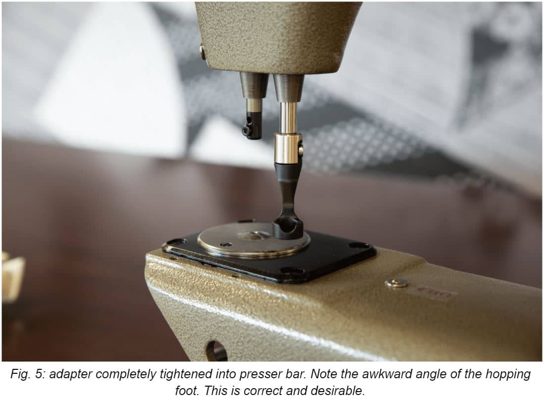
3 Foot Setting Checks