
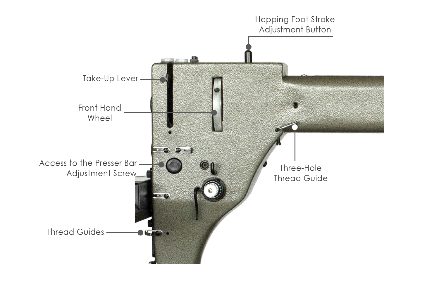
Front of the Machine
Take-Up Lever: Moves up to pull out any slack in the top thread as the stitch is completed.
Front Hand Wheel: Used to manually raise or lower the needle.
Access to the Presser Bar Adjustment Screw: Adjustments to the presser bar are made via the presser bar adjustment screw, which is covered in this article.
Thread Guides: Used to guide the thread during stitching to prevent thread breaks.
Three Hole Thread Guide: Used to guide the thread during stitching to prevent thread breaks. Use the first and last holes only. The first hole is threaded from the bottom up and the third hole is threaded from the top down.
Hopping Foot Stroke Adjustment Button: Used to adjust the hopping foot, which is covered in this article.
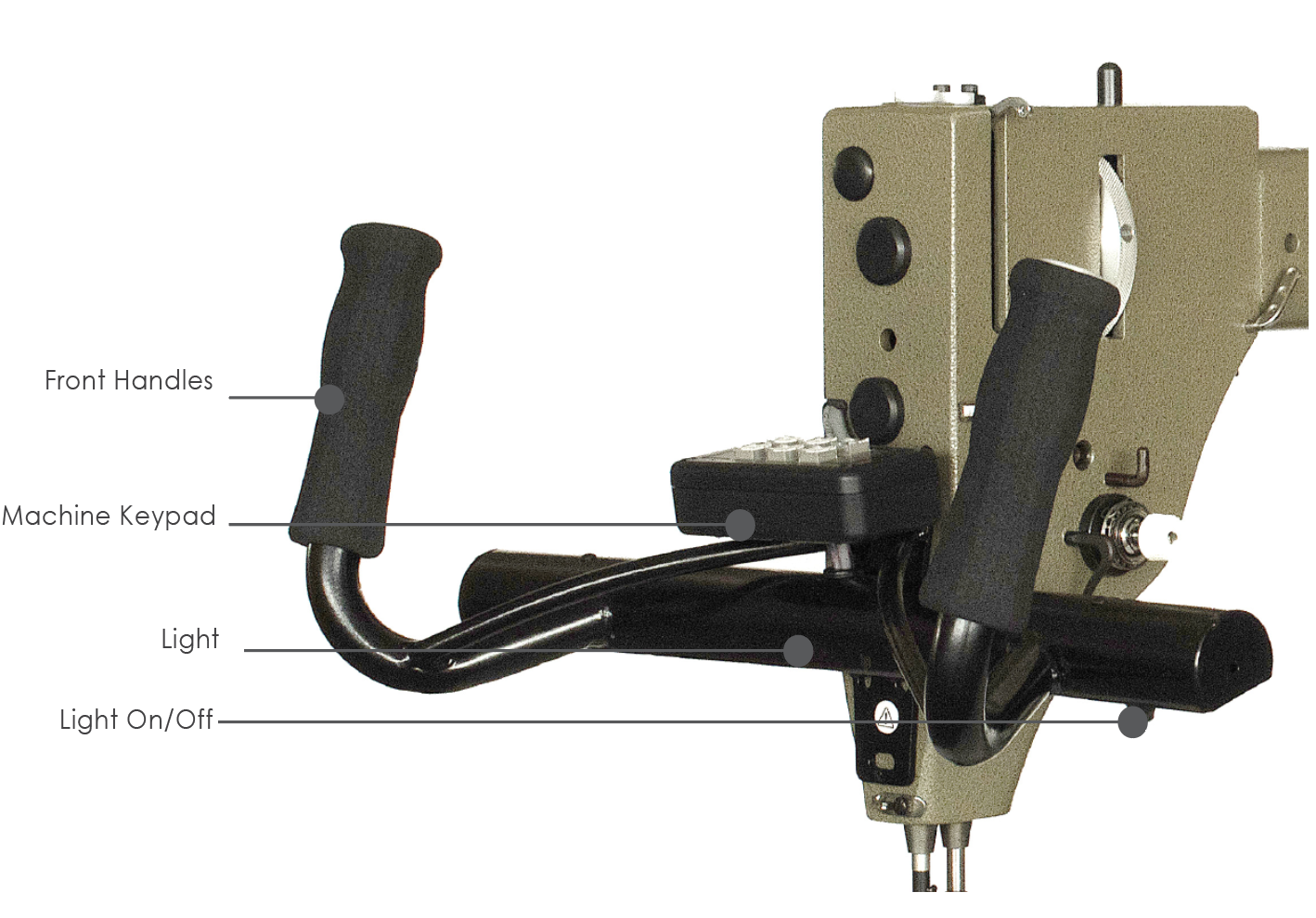
Front of the Machine
Front Handles: The front handles are used to move your machine manually.
Machine Keypad: The machine keypad is used to interact with the CreativeStudio® software
Light: The light illuminates the quilting area with natural (LED) or black light (UV).
Light On/Off: Pressing the light on/off button on the light will toggle it between natural light and the black light and turn the light off.
If you have a complete Vivid Light System, you will also have a light on the throat of the machine that can be switched from natural light to black light.
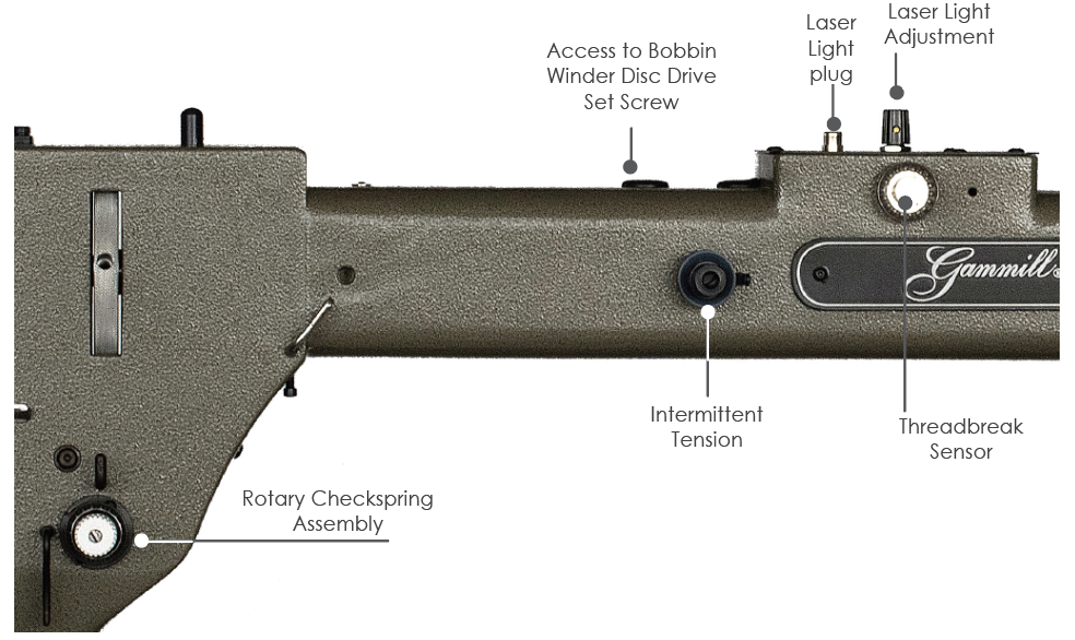
Side of the Machine
Rotary Check Spring Assembly: The housing for the check spring. The tension on the spring is set at installation. The white knob should be flush with the post and should not be turned.
Intermittent Tension: The intermittent tension is used to set the top thread tension. All adjustments to the tension are made using the intermittent tension discussed in this article.
Thread Break Sensor: When a thread break occurs, the thread break sensor measures thread movement and triggers an alarm when thread movement stops.
Top of the Machine
Access to Bobbin Winder Disc Drive Set Screw: The access location for the bobbin winder driving disc set screw.
Laser Light plug: On the top of the Statler is a plug in for the laser light.
Laser Light Adjustment: This can be used to adjust the brightness of the laser light.
On the opposite side of the machine is the Onboard Bobbin Winder, which is covered in this article.
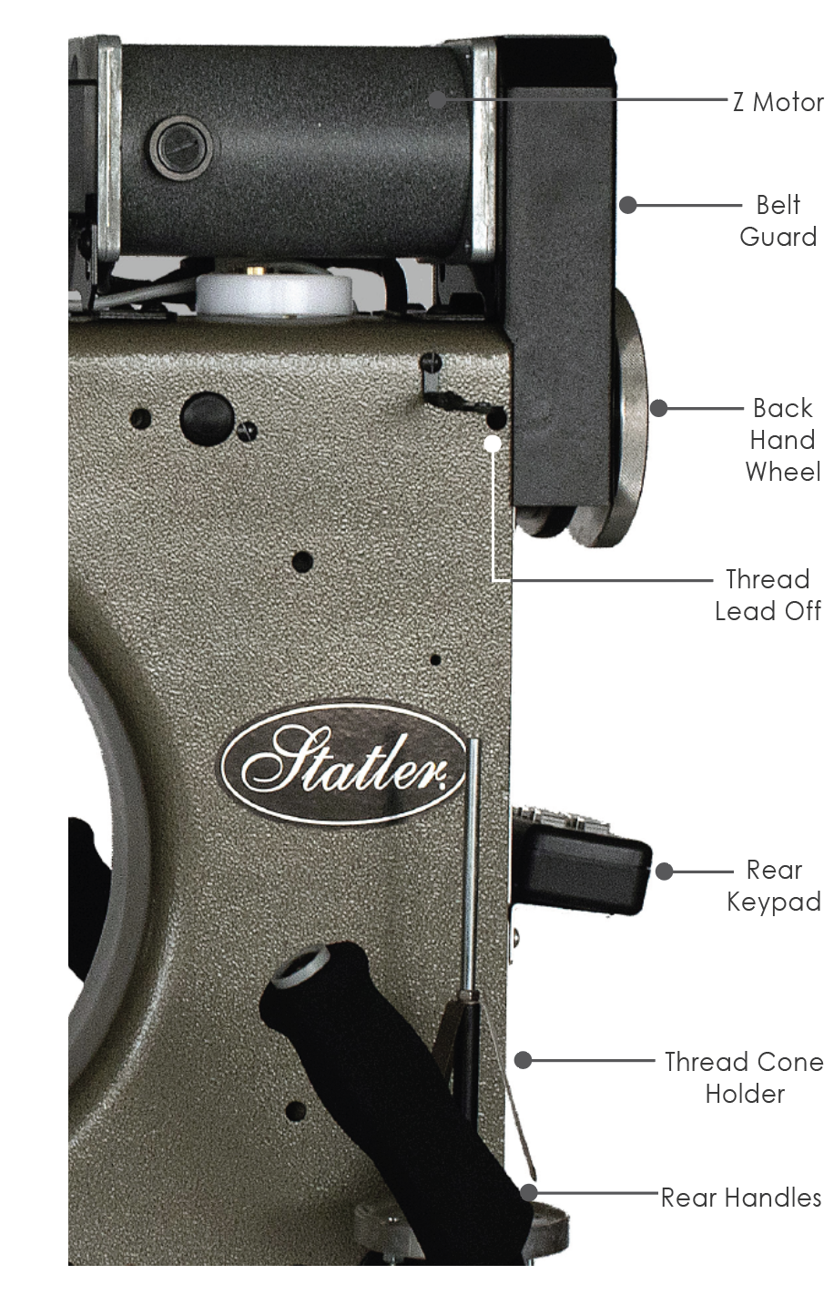
Back of the Machine
Z Motor: The Z motor powers the stitching mechanisms of the machine.
Belt Guard: The belt guard shields fingers, hair, jewelry, and other objects from becoming caught in the motor belt.
Back Hand Wheel: The back hand wheel is used to manually raise and lower the needle.
Thread Lead Off: The first thread guide, the thread lead off, is located just above the cone and is threaded from the bottom up, then from back to front.
Rear Keypad: The rear keypad allows you to control the CreativeStudio software from the rear of the machine.
Thread Cone Holder: The thread cone holder securely holds the cone of thread to feed thread to the machine for stitching.
Rear Handles: The rear handles allow you to drive your machine from the back.
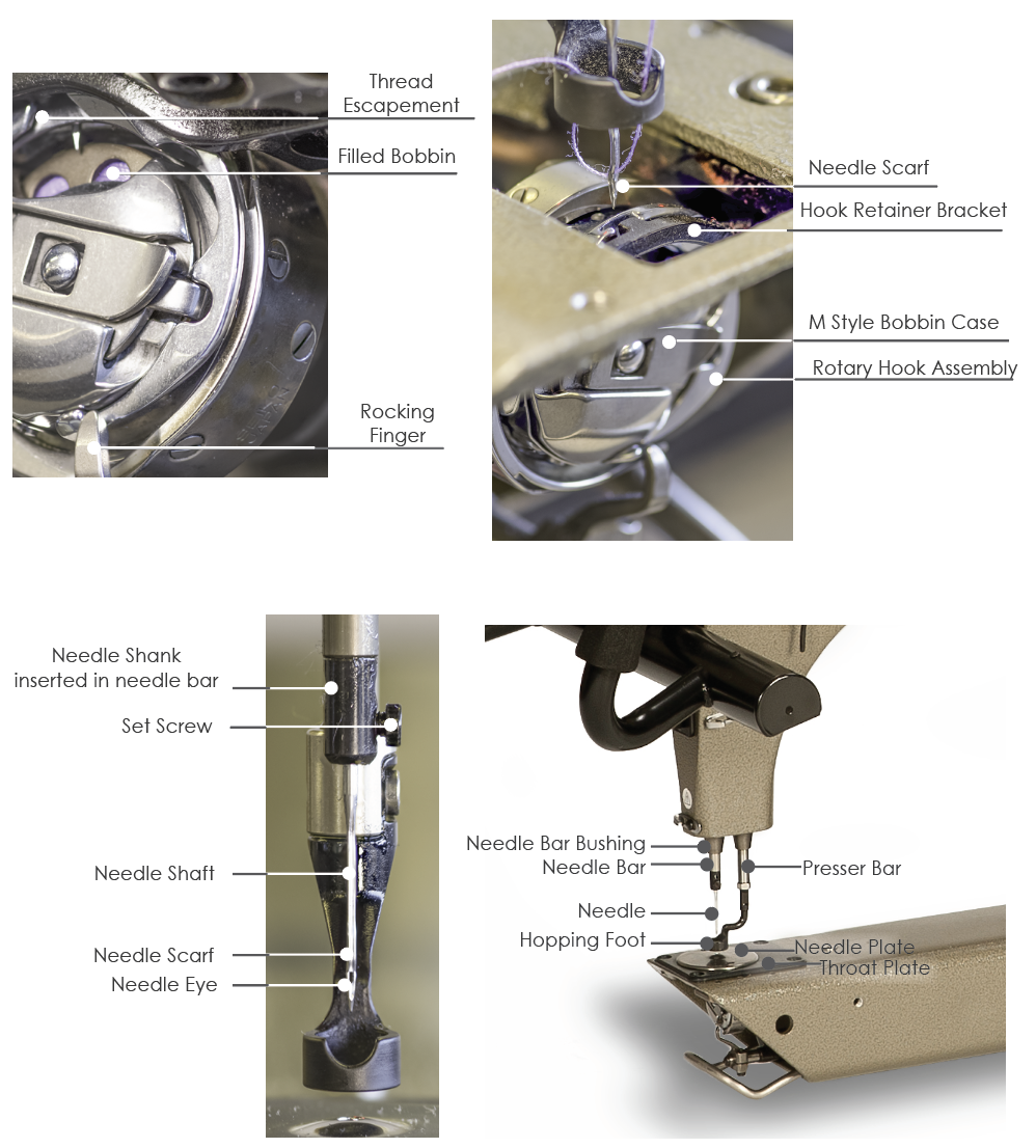
Needle Area
The following photos identify the parts related to the needle and the process of making stitches. This process is covered in greater detail in the article on needles and stitching.
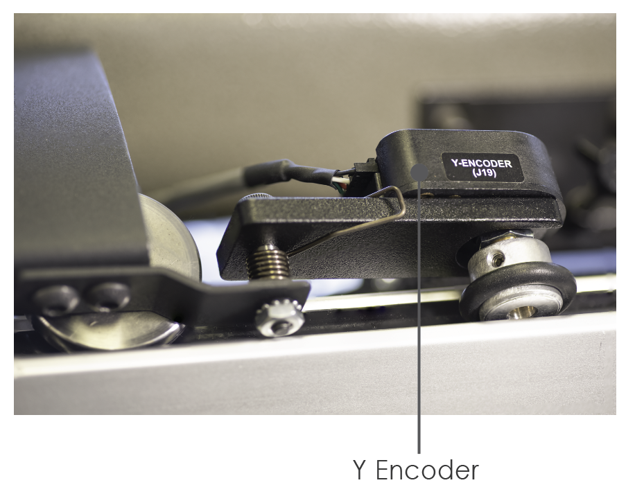
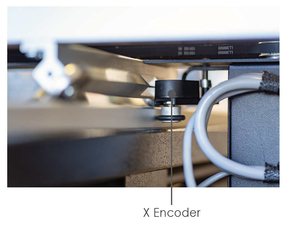
Encoders
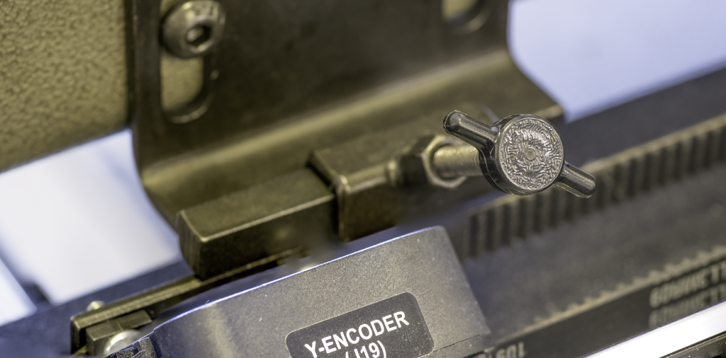
Stitch regulation is controlled by your machine’s encoders while stitching in hand guided mode or baste. The Y encoder controls stitch length vertically and the X encoder controls stitch length horizontally. The encoders are located near the wheels of the crosstrack on the X and Y axes.
 |
 |
Wheels and Crosstracks
The Crosstrack carries the machine head. Wheels move the machine head along the crosstrack. And the crosstrack moves along the Breeze Track.

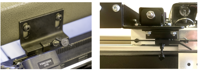
Dropping the Belts
Dropping or disengaging the belts on the Statler or Elevate machine will allow the user to handguide the machine with ease.
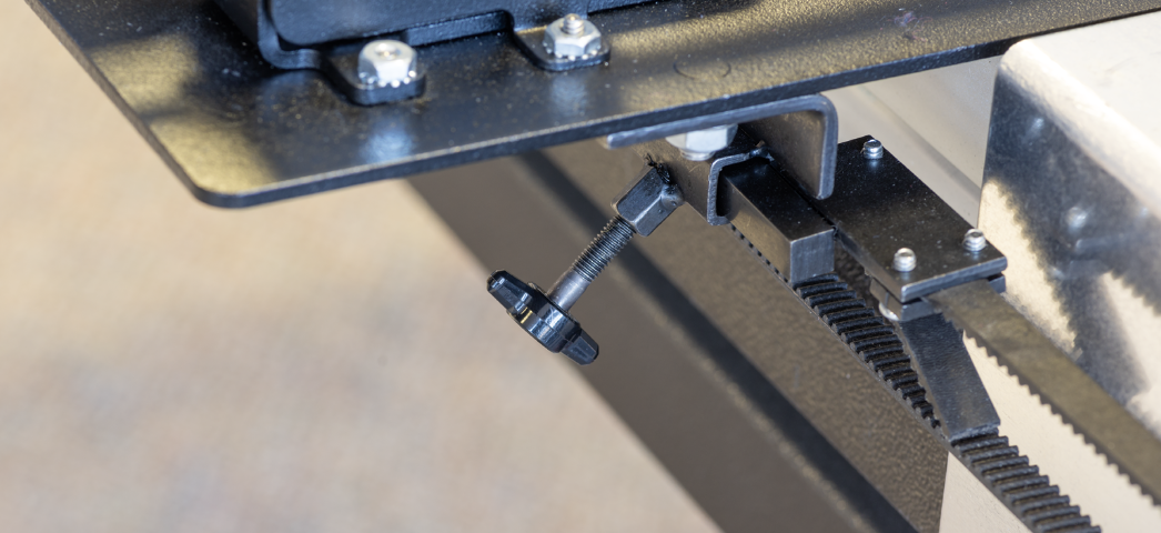
There are two belts to disengage with T screws. One is on the front of the machine and the second, on the Y encoder side.
|
Turn the T screws counter-clockwise |
 |
|
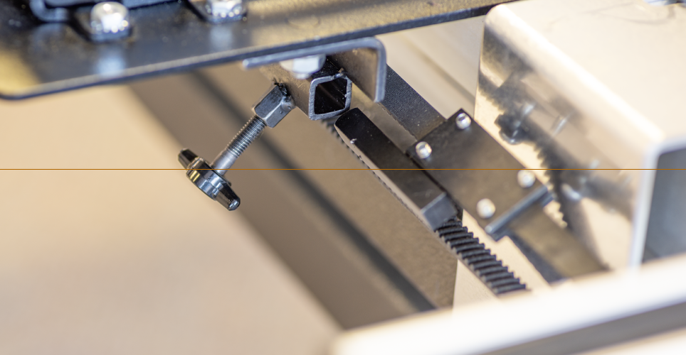
Remove the belt connector from the insert. |
 |
|
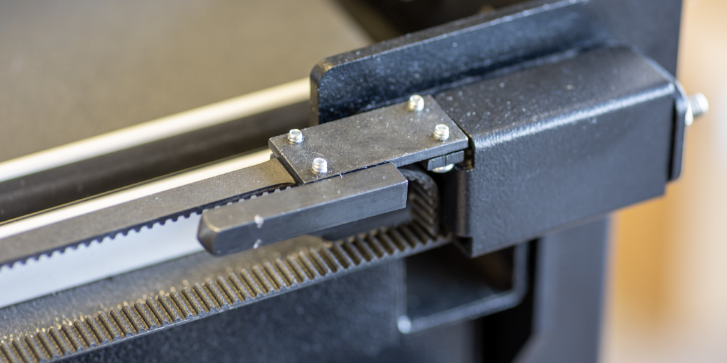
Pull the belt until the connector is out of the way of stitching. |
 |
|
Repeat the process with the second belt. To reengage the belts, replace the connector and tighten the T screw. When reattaching, make sure the belts are straight and have not twisted. |
 |